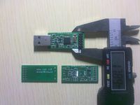
Universal UART ISP dongle
Contents
What is it?
Many new microcontrollers can have their firmware upgraded when they're in final circuit (In-System Programming). It's a nice feature, and usually you only need UART RX, TX, a pin to select either application or bootloader entry on boot. That makes the final pin RESET.
This is supported at least on lpc11xx, lpc13xx, lpc213x, stm32, and luminary stellaris ARM microcontrollers. In fact, it wouldn't be too hard to create your own bootloader that does it.
The common solution is to just hook UART to RS232 level shifter and that to the PC. You also need two switches then, which are sometimes "created" with RTS/DTR control lines.
That solution is described at Lpc_isp_dongle.
Why reinvent a serial cable?
There are a couple of problems with the cable approach:
- Pressing switches every time you want to upgrade sucks.
- The alternative is abuse of RTS/DTR, and that makes using the same serial cable for ie. debugging tricky.
- Supports one device unless you compromise with an elaborate switch setup.
When planning for this, the most important features were:
- No hand to hardware interaction - everything needs to be able to be scripted.
- Support for programming multiple devices without replugging anything.
Solution
Hardware
Besides the power pins, we connect three shared pins to every device: UART RX, TX and boot select. The RESET line needs to be connected to every target separately, and it basically acts as chip select. Only one device is active at the same time.
From hardware point of view the dongle is basically a usb<->uart (3.3V) bridge with a couple of GPIOs.
PCBs were made by these dudes: http://iteadstudio.com/store/index.php?main_page=product_info&cPath=19_20&products_id=173 They're super cheap, and quality seems decent. It does take around 5 weeks to get PCBs to home, so that might suck.
Software
One would think the VCOM (virtual com port / USB CDC ACM) part is easy, since NXP published examples for this exactly. Except they don't work very well when you push them to transfer lots of data. With a few sleepless nights and lots of googling, I managed to fix them and learn more about USB than I ever wished.
What's left is the control of GPIOs. I wanted the dongle to be "transparent uart dongle", so I had to use some trick to enter so-called command mode. The typical solution I've often seen for problems like that is: <delay><special sequence><delay>. I found it simpler to just send a BREAK signal to VCOM and plug a handler in there.
Command handler itself is rather simple with only three commands:
- gpio - returns hex number, where set bits mean pin high, reset pin low
- gpio <hex arg> - sets pin levels according to bits in argument
- quit - exit command mode
So, what's in it for me (the reader)?
Well, hopefully you got some ideas. Or maybe it got you interested in this product I'm trying to sell (but first I need to make it! :P), haha.
