Simple Inverter
Obligatory warnings
High voltage - Voltage at the output end of this circuit exceed the maximum safe limits for sticking your tongue on it. Seriously though, we're talking a few hundred volts which could quite easily kill you.
Moderate current: During testing I had this baby sucking up over 8Amps from my power supply when under load, and fried a few components during prototyping. A few resistors actually CAUGHT FIRE. Components that feed the transformer will need to be beefy and/or attached to a heatsink, and rated to withstand high constant currents.
Introduction
I decided to have a go at building an inverter to push out ~240V AC from a 12V source. My 12V source is a trusty old computer PSU, although I suppose this should work just as well from a battery.
The idea behind it is fairly basic: generate a 50Hz signal to drive some transistors to switch the 12V DC source on and off, and feed this into a step-up transformer (1:20 ratio). The transformer im using was pulled from an old 750VA UPS, so it's designed to do this job. The primary has a centre tap so i'm using a half-bridge design here, I might have a go at building a full-bridge when I get some P-FETs in but for now im using two P60NF06's as the drivers.
Originally I tried switching these with a square wave generated from a 555 running at ~50Hz, this worked, but the output waveform was poor and full of harmonics, it struggled to light a 60W light bulb. I figured I would get much better power throughput if I used a Sinusoidal input, so I grabbed a few LM324's (Quad op-amp) and set to work.
This final design uses only one LM324.
How it works
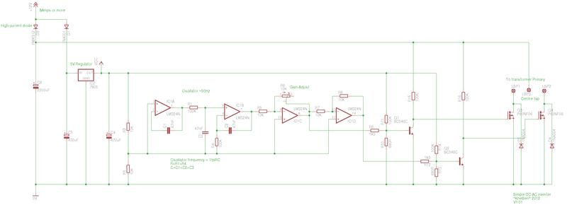
The 5v regulator runs the LM324 (I figured it would run smoother if it had a dedicated stable supply free of feedback from the toroid), with a voltage divider providing a virtual ground at 2.5v for the op-amps to reference. This negates the need for a dual-rail supply and is something I can get away with here because the op-amps wont be sinking or sourcing any significant currents to the virtual ground.
The first two op-amps form a quick and dirty sine wave oscillator, for its simplicity the output it generates is surprisingly clean, and close enough to 50Hz (Actually its around 40Hz with the components I’ve used but that's just fine for testing).
The frequency of the oscillator can be calculated as F=1/PiRC. With the components I used it's a little on the high side... it comes out to about 67Hz, although in practice this was a little lower.
the third op-amp primarily acts as a buffer to prevent loading to the oscillator that could distort the signal, however I have also included a variable resistor to adjust the gain. This allows me to vary the output power quite easily.
The final op-amp inverts the signal for the second fet (effectively a 180 degree phase shift).
The two BC546 transistors are biased to remove the 2.5V DC offset of the virtual ground and drive the FETs. On reflection I may be able to remove this stage and drive the FETs direct from the opamp output (properly biased of course).
The primary centre tap of the toroid is connected to the big 2200uF tank capacitor, and is protected from feeding back into the supply voltage by a diode. I have used a schotkey diode for its high current rating (im not sure what it is as I haven't looked at the datasheet), this thing pulls a LOT of current at full load so be warned.
The FETs are connected to the other two primary leads, and alternate switching. They do get warm in operation, especially at high load so a heatsink is required. Although the fets have an internal protection diode, I have added external protection diodes to be on the safe side.
Pictures!
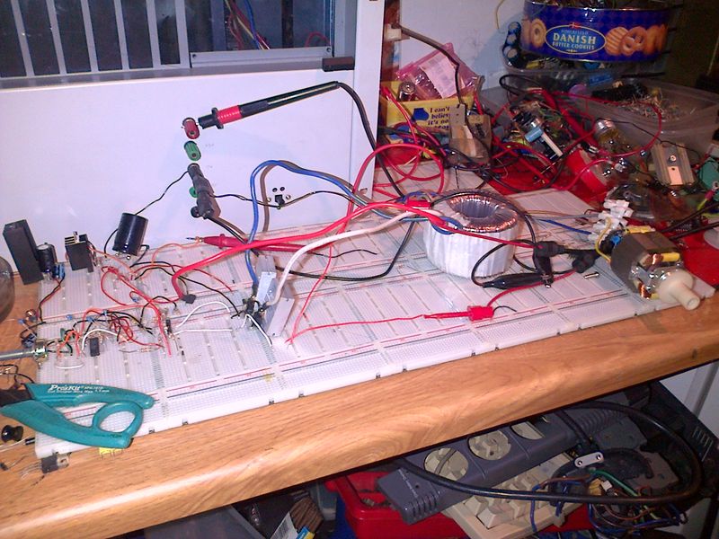
Here's a picture of the whole setup running a small mains powered motor. note the big juicy toroid. It might be a bit hard to see from this photo, but the motor is running quite happily.
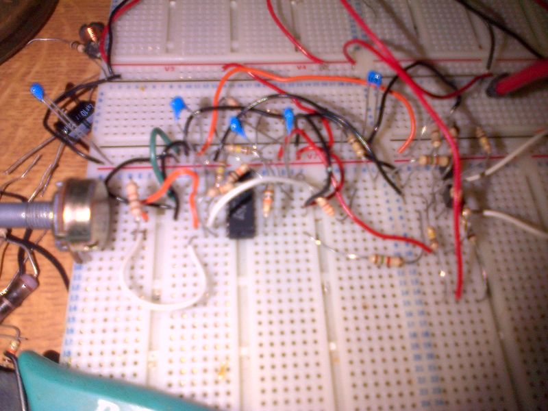
Here's a closeup of the oscillator stage.
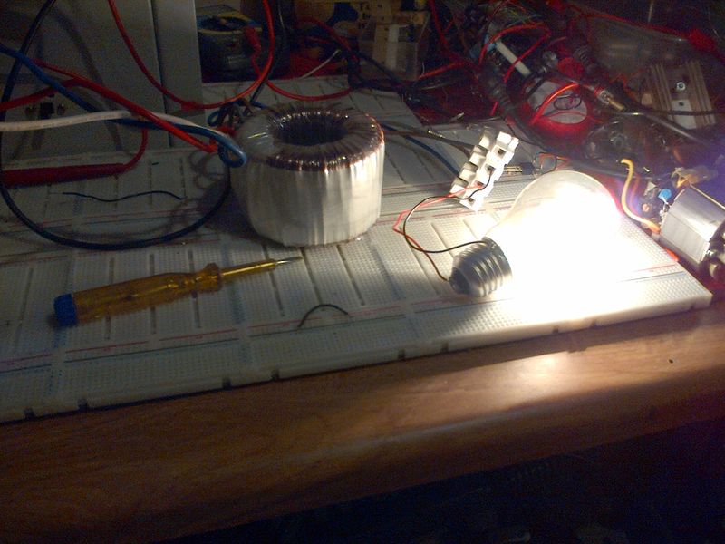
This is probably a better demonstration of the output, a lightbulb!
All in all it works rather well so far. It can power a 240v 60W light bulb quite nicely, and even a small motor. The variable gain control allows easy adjustment of the power output to dim the bulb or adjust the speed of the motor. With the light bulb on full the circuit is drawing a bit over 6A from the supply. It draws closer to 8A with the motor connected.
To Do
Upload readings from the fet gates and toroid output.


