Flow-X IO interface board
Contents
- 1 So what is this anyway?
- 2 Covered I/O =
- 2.1 2 RS-232/RS-422/RS-485 serial ports
- 2.2 1 PT100 resistance temperature measurement input
- 2.3 3 analog inputs, configurable for current/voltage
- 2.4 2 analog current-outputs
- 2.5 16 open-collector digital I/O pins
- 2.6 On the PC
- 2.7 so this is a test
- 2.8 subsection again
- 2.9 subsection 1
- 2.10 subsection 2
So what is this anyway?
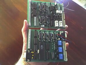
Below follows a description of a nice hobby-project to make an interface board that basically sits between a PC and an I/O module, to read module-outputs and stimulate module-inputs.
Flow-X module
This is a small but very nice modular flowcomputer for the oil- and gas-industry; since I toy with/at this thing at work, why not make a little something to make Life a bit Nicer.
Interface-board
It would be nice to test test and provide stimuli for various digital/analog I/O's on the module from a PC, while meanwhile trying to keep it safe, or rather fool-proof in case I/O is misconfigured (i.e. misconfigured 'low' output connected to 'high' output), because we all make mistakes.
Some of the module's I/O is read/stimulated by the interface-board directly, while for other signals, the board only multiplexes signals or even simply passes them through to a host-PC. All I/O the board is capable of reading/stimulating itself, is passed to/from a host-PC using a serial protocol. Remaining I/O to be read/stimulated is psysically connected to the board, where it is multiplexed or just passed through to the module.
Covered I/O =
The board reads/stimulates the following I/O on Flow-X:
2 RS-232/RS-422/RS-485 serial ports
These are simply passed through from module to host-PC; interface-board only provides a DE-9 connector for convenience sake.
1 PT100 resistance temperature measurement input
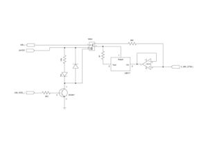
Resistance (or temperature) for the module can be specified by supplying an external voltage (0..5V) to the board. The signal is buffered by an opamp and then used to drive a high-intensity LED glued to a LDR. Current is limited to 27mA, just because we are very nice. In fact 27mA is insanely high come to think of it.
3 analog inputs, configurable for current/voltage
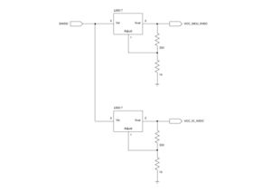
In case of current-input, the module basically reads the voltage over an internal shunt-resistor. This current can be controlled by feeding the board with a voltage (0..5V), which is buffered by an opamp and fed into the shunt. Current is again limited to 27mA; this is low enough as to not cause damage in the module. V/I will not be linear, mainly because of the current-limiter (LM317), but this can be compensated by software.
In case of voltage input, the board simply places a safety-resistor in between the voltage (0..5V) offered to the board and the module. A relais on the board switches between current/voltage modes.
2 analog current-outputs
To read outputs from these 4..20mA outputs, the board simply contains a 220ohm shunt for each, and outputs the voltage over each shunt as output-level. Software will do conversion back to current.
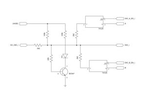
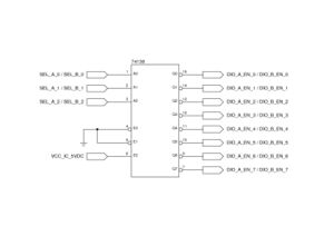
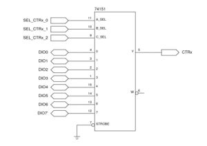
16 open-collector digital I/O pins
Because the module only has open-collector I/O's,
=== serial ports
On the PC
so this is a test
text text text text text text text text text text text text text text text text text text text text text text text text text text text text text text text text text text text text text text text text text text text text text text text text text text and here's a thumbnail: text text text text text text text text text text text text text text text text text text text text text text text text text text text text text text text text text text text text text text text text text text text text text text text
lala.
subsection again
subsection 1
subsection 2
so ok.
--Michai
