Hotplate
DIY Hotplate
WARNING!!! This project uses high-voltage mains electricity. Excercise extreme caution if you plan to carry out this project on your own. Mains voltage can kill
A hotplate is a useful device to have in any workshop, it can be used to solder and de-solder SMD boards quickly, heat liquids, solder over large areas that a hand-held iron just wont cope with, or simply to keep your coffee warm on those late-night projects.
My primary concern about this project was whether the iron could reach sufficient temperature to be of any use (particularly melting solder), however a proof-of-concept test revealed that it could both exceed the required temperature, but also maintained this temperature for quite a while after power-off.
Parts
The main component of this project is an old clothes iron. The best type to get is a non-steam iron, as these have a completely flat base without holes (where the steam would come out). I acquired one of these from my mum, who had one laying around in the back of her cupboard underneath some sex-toys, but you could probably pick one up from a car-boot sale or yard sale for a few pence).
Next you need a base to mount the plate on. since a clothes iron is designed to be hot-plate down, you will need to mount it upside-down on some heat-resistant material. For this particular iron I was able to use a part of the iron itself.
Control circuit. I'll be coming to this a bit later, but the idea is to maintain the hotplate within a narrow range of a pre-set temperature.
Proof of concept
The initial proof of concept model was quickly thrown together with little safe-guard for safety or control. The 1000w heating element is wired directly to a plug, the only control is the switch at the plug socket. Initial testing of the plate was carried out by placing a piece of solder on the plate, and the plate was switched on. The solder melted after about a minute and the power was switched off. At this point I placed a spare SMD board on top of the hotplate, and within a few seconds was able to remove all the components neatly.
<youtube size="large" align="inline">WZq-asBCZkY</youtube>
Updates
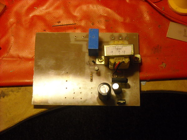
23-07-2009 Being bored one night I started building a controller for the hotplate. Lacking some vital tools I improvised and used a gold metallic pen as an acid resist (I was actually somewhat surprised to discover that it was in fact acid-resistant), the board is pretty rough, but it does the job. There is no actual controller on this board, that will be done on a separate board, this just supplies the +12v for the relay, +5v for the logic and of course, has the relay to power the hotplate on/off, and a simple temperature sense circuit.
Here is the (unfinished) board; originally it was to just have a 5v regulator on board but this didn't provide enough juice to flip the relay, so this was replaced by a 12v regulator, and some copper track was later cut by hand to accommodate a second regulator running at 5v.

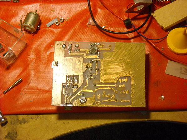
And the underside

Yes I know it looks like a 5 year olds attempt at "my first circuit board", but it works... at least it did after a few modifications. observant fellows will notice that i cocked up around the relay area, with the heater output in the "normally on" position. This simply would not do as a failed controller would cause the heater to go into overdrive and probably burn out whatever I was working on. Some modifications with a dremel and fancy soldering solved this, and it is now in the "normally off" position. Pics will follow at some point of the modified board.
ToDo
Upload power supply
Design and prototype controller board (probably going to be PIC-based since I have one spare)
Mount everything in a case (everything should fit into an old computer PSU housing with the iron mounted on top)