Universal CAN Modules
Contents
The universal CAN modules
Ever thought of an application that would be based on asynchronical transmission of short messages? Cool message prioritizing would also be handy? Just add cheap
data medium and long bus range with a possibility to add over 530.000.000 ECU nodes to it... Put some of extremely effective error managing ability to the jar as well.
Mix it all together with a lot of other tiny incredients that only make the whole thingie spicier and here it is: [http://en.wikipedia.org/wiki/Controller_area_network The
Controller Area Network].
Knowing all the strong sides of this praisefull technology, a lot of companies base their applications on CAN. The idea was to build universal CAN modules, which would
let user either connect any digital device to already working CAN bus (and interfere with it) or build whole new standalone CAN based app as he wishes to. The CAN
modules i present here are a bridge between CAN bus and any other digital interface that uses less than 13 data lines directly. Additional I/O expanders, external A/D
converters, etc. can of course bring some more funcitonality to the device. But everything in its place...
The hardware
I did the design while i was still studying so economics were the main criteria when thinking of the whole project. Microcontroller was a must. Internal CAN controller
would simplify the board. Also debugging interface couldn't be expensive. I browsed manufacturers' sampling offers and ST Electronics had
what i needed - the STR712 MCU for free for testing. It has (apart of already mentioned internal CAN controller) whole lot of hardware interfaces builtin (i.e. I2C, BSPI,
USART, etc.) so the software part is way easier to manage. Talking of that - ST released it right with a free to use software library - really usable lib for a quickstart
(includes all STR712's peripherials management functions coded in C). ARM core guaranties fast data processing for software implemented interfaces (yeah, trully
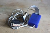
universal modules must allow this as well). Did i already mention the cheapass debugging interface? Yes, DIY JTAG is a ~2EUR thingie here. So ok - the heart has been
choosen.
The prototype
It was my first ARM related project. Also first time i got in touch with CAN. Never used JTAG before. My C experience was less than a basic back then (gained to basic
level already in meantime!). So I decided to build a prototype.
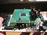
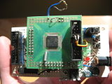
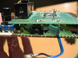
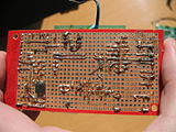
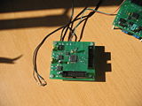
It was just a simple two-boards set. TQFP64 (and TQFP-more) to standard 2.54mm soldering grid board attached on top of other universal board via goldpins. The
first board only contains MCU, RTC quartz, some caps underneith it and an IDC connector - directly soldered to few controller's I/O's. The latter board has JTAG
interface (also IDC conector), PSU, few LED diodes, switches/buttons, potmeter, clock for MCU and CAN transceiver on it. All worked as a charm and i learned
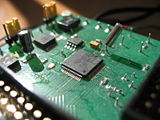
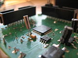
something about what I was just stepping into (thank you JTAG!). Here are some pics of it:
The schematics and PCB
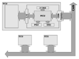
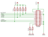
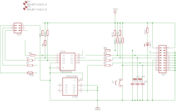
On first picture there's a block schematic of how the module should fit whole CAN application. Each module has PSU, JTAG interface, I/O's connector, clock generator
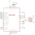
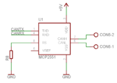
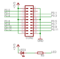
and CAN transceiver onboard. Latter pics contain idea schematics. Whole circuit is very simple - thanks to a lot of hardware interfaces controllers builtin STR712 chip by
ST. It's basicaly just a basic setup to startup the MCU (clock generator, few capacitors and resistors). I added voltage regulators and rectifier-bridge on board, so that i
can connect the module in different places (universality, remember?), not caring much about the available supply voltage level/type available in there (please read the
bugs section regarding power supplying). I decided for twisted copper pair cable CAN medium (which is most common) so I've put Microchip's CAN transceiver
MCP2551 in there as well. Remaining parts are: RTC quartz (see bugs section), voltage-present indicating LEDs, some other LED connected to I/O port for software
signalization purposes and connectors. For JTAG i used standard (for the wiggler's clone i've been working with) IDC20m connector. Same was choosen for I/O
interface. For power supplies and CAN physical interface i decided to go the screwed terminals way. That way it's (again) easier to fit the existing app's interfaces when
connecting to one.
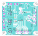
Last image in here is the PCB layout. I wanted it to be as cheap as possible so first i wanted to do it myself. This is why i aimed one-layered board. I managed to fit it
on 60x65mm. board with just three short-wires on back of it. I found the cheap PCB-house later, so i decided to order nice looking proper PCBs
from them. Ordered four boards, got six of them for like 3EUR / piece IIRC. Quality's very good IMHO, so it was good deal.
The ready devices
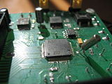
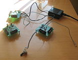
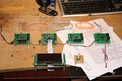
Here are some pics i took when i was still working on the demo application. Back then i used rotary encoder attached to one of modules to set LED blink rate on other
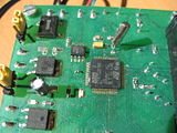
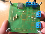
CAN node. Was quite fun to get to know it actualy works! Few shots present the montage details as well. Screwed terminals for CAN / supply voltage interfaces are
accessed from bottom side of boards. Also notice the way i soldered IDC connectors - now I'd (at least try to) use the SMD ones. I also found the thru-hole capacitors
way cheaper than those in SMD packages, so... You can see it by yourself. For final look please see the working application section. [link]
DEMO application
The main reason why CAN was invented is to simplify car electric installation. I wanted the demo application to be somehow similar to this concept. What i came with is
a set of four modules connected to one CAN bus:
- LCD module - basicaly the main module of whole application. It not only diplays the current time and temperature but also the thermostate's set edge value and
operation menu for user. This node also processes the data sent from all other nodes and makes decissions on how the data should be used like. LCD interface was
implemented in software.
- RTC module - sends current time frame (it's set by user via encoder and lcd modules; works by using the internal RTC of STR712) to be displayed on LCD. This
module also makes use of onboard LED - it works as an thermostate-simulator: LED glowing indicates thermostate working. I've used ST's library to set up RTC.
- Encoder module - that allows user to interfere with whole application: i.e. setting current time and edge temperature for thermostate. Interface implemented in
software: polling.
- Sensor module - DS18B20 sensor has been attached to this node. 1-Wire interface - i wrote some simple lib for it.
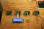
Here are some pics. First one shows data flow between nodes diagram. Latter ones are the working app. Iscrewed modules onto plexi board - it looks quite fine if you
ask me but have a look yourself. BTW I've also tested UART but i didn't take any pics of it working.
I once recorded this clip to present you my work. Michai detected a lot of russian english there... No need for futher comments on this one. Let it be so.
<youtube align="left">YzJDEWbhf6g</youtube>
JTAG interface
I don't even remember where i found the first schematic of it, but it is really usable and praiseworth thing. The JTAG. Programming IDEs support JTAGs so it's easy to
make it work (open source drivers ar there as well). It allows to upload code to MCU as well as it helps with debugging, especialy at the very beggining, when there's
no UART around. Michai gave it a closer look once. [link]
Bugs
Yes, board has some bugs i got to known of already:
- I 'forgot' to add capacitors between GND and both legs of RTC 36khz quartz, so internal RTC won't work without some soldering under module's PCB.
- CAN transceiver requires %VDC power supply. STR712 requires 3.3VDC to work. There are luckily no problems with transmitting data between those two chips
(which i found out while testing the prototype) but board could be simplified (one voltage regulator less on board) if i choosed to switch to 5VDC MCU (yes, there are
things like that). The way I did it may not be elegant nor smart but i already had the free-samples chips and i didn't want to throw them away.
- I had some problems with changing I/O P0's states while working on LCD module of my demo application. Problem was whole port didn't want to change its state on
all 13 lines at once. I didn't sniff around too much - just changed the port's value with two instructions (half of lines at a time). Still not sure what caused it.
/Pit
