Stargate switch v2
Description
This is a more advanced version of the v1 stargate switch.
TX
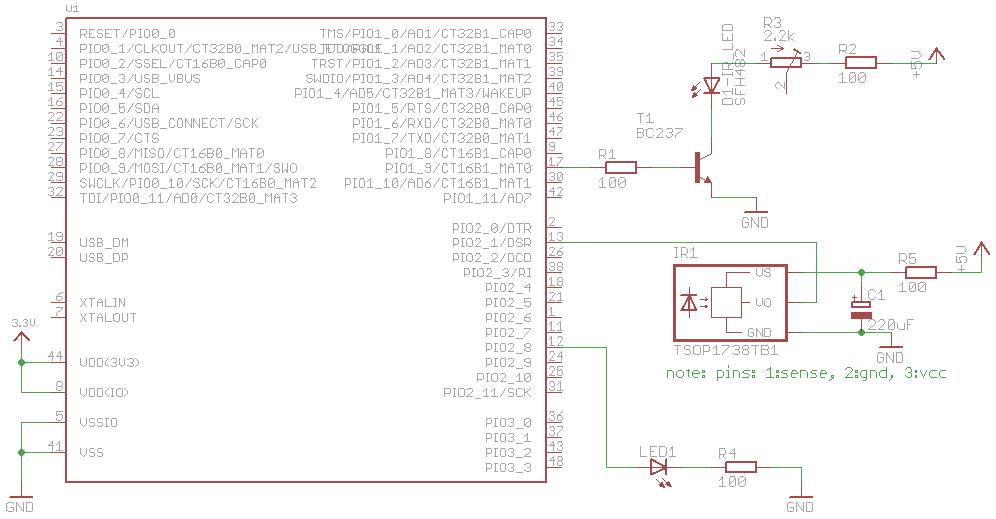
Instead of just a simple 38 KHz square with a 555, I used an MCU (lpc1343) to create the modulated signal. I also used a proper RC5 code to make it noise resistant. RC5 is well described (see references), and the code does not contain any magic.
RX
Receiver part is, like in v1, a bought IR sensor with a demodulator (SFH5110, TSOP1738, TSOP2438). Its output is 1, and when it detects a 38 KHz signal it pulls output line to GND. Since it delays a bit, I decided to sample it after the end of outputted square/0 signal.
HW non-trivialities
It was non-obvious to me why this did not work on first tries. It was quite a basic problem - the IR sensor needed 5V powering. Of course this then means the GND for module and MCU should be shared. And that the MCU pin must be 5V tollerant.
To limit the IR LED angle, I used a heatshrink to make a narrow beam. Sensitivity (LED radiance) can be changed with the trimmer pot, which is a current limiter to LED.
I've had lots of problems related to sensor powering. Some of which I didn't quite understand (better power supply resulted in more noisy sensing?). In the end I noticed a resistor in TSOP2438 datasheet (there was none in other datasheets). The R5 and C1 are VERY important here. C1 could probably be lower, the value remains from before-R5 times.
Schematic
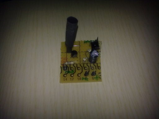
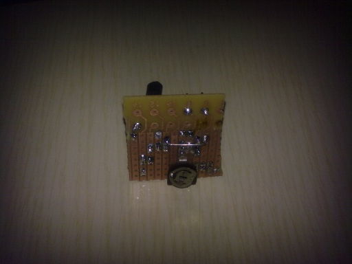
Pics
Silly module for testing: 5v, gnd, pwm input, sensor output.
And for people not stuck in ninetees, a video clip: <youtube width="512" align="left">WHrmrGVljhY</youtube>
(http://www.youtube.com/watch?v=WHrmrGVljhY)
Code
<syntaxhighlight lang="c">
- include <types.h>
- include <compiler.h>
- include <gpio.h>
- include <interrupt.h>
- include <mach/lpc13xx_gpio.h>
- include <mach/lpc13xx_regs.h>
- include <board.h>
- include <string.h>
- include <stdio.h>
/* timer irq must get called every 889us, pwm has 26.316us duty cycle */
- define MODULATION_FREQ 38000
- define PULSE_LEN 889
struct lpc13xx_tmr {
volatile u32 IR; /* 0x0 */
volatile u32 TCR; /* 0x4 */
volatile u32 TC; /* 0x8 */
volatile u32 PR; /* 0xc */
volatile u32 PC; /* 0x10 */ volatile u32 MCR; /* 0x14 */ volatile u32 MR0; /* 0x18 */ volatile u32 MR1; /* 0x1c */
volatile u32 MR2; /* 0x20 */ volatile u32 MR3; /* 0x24 */ volatile u32 CCR; /* 0x28 */ volatile const u32 CR0; /* 0x2c */ u32 _reserved0[3]; volatile u32 EMR; /* 0x3c */ u32 _reserved1[12]; volatile u32 CTCR; /* 0x70 */ volatile u32 PWMC; /* 0x74 */ };
- define TMR16B0_ADDR 0x4000c000
- define TMR16B1_ADDR 0x40010000
- define TMR32B0_ADDR 0x40014000
- define TMR33B1_ADDR 0x40018000
struct sequence {
int len;
int pos;
/* these are MSb first */
u8 tx[4];
u8 rx[4];
};
static struct sequence _seq;
static struct sequence *seq = &_seq;
static struct lpc13xx_tmr *t1 = (void*)TMR16B0_ADDR; static struct lpc13xx_tmr *pwm = (void*)TMR16B1_ADDR;
- define SENSOR_PIN GPIO_2_1
- define LED_PIN GPIO_2_8
void __interrupt timer16_0_irqhandler(void) { int pos = seq->pos; int bit = gpio_get(SENSOR_PIN);
/* clear interrupts */ t1->IR = t1->IR;
/* sensor output is reversed */ if (!bit) seq->rx[pos/8] |= 1 << (7-pos%8); else seq->rx[pos/8] &= ~(1 << (7-pos%8));
pos++; seq->pos = pos;
/* stop */ if (pos == seq->len) { pwm->TCR = 0x0; pwm->TC = 0; /* this turns the led off */ t1->TCR = 0x0; return; }
if (seq->tx[pos/8] & (1 << (7-pos%8))) { pwm->TCR = 0x1; } else { pwm->TCR = 0x0; pwm->TC = 0; /* this turns the led off */ } }
static void setup_timers(void)
{
LPC_SYSCON->SYSAHBCLKCTRL |= SYSAHBCLKCTRL_CT16B0;
LPC_SYSCON->SYSAHBCLKCTRL |= SYSAHBCLKCTRL_CT16B1;
gpio_init(SENSOR_PIN, GPIO_INPUT, 0); LPC_IOCON->PIO1_9 = 1; /* CT16B1_MAT0 */
/* reset */ pwm->TCR = 0x2; pwm->TCR = 0x0;
pwm->PR = 0; pwm->MR0 = (CONFIG_FCPU + MODULATION_FREQ) / (MODULATION_FREQ*2); //pwm->MR3 = (CONFIG_FCPU + MODULATION_FREQ/2) / MODULATION_FREQ; pwm->MR3 = pwm->MR0*2; pwm->MCR = 2<<(3*3); /* reset on MR3 match */ pwm->PWMC = 1<<0; /* PWM on MAT0 */
t1->TCR = 0x2;
t1->TCR = 0;
t1->PR = 0; t1->MR0 = CONFIG_FCPU/1000000 * PULSE_LEN; /* with 72 MHz this goes just under 64k */ t1->MCR = 3<<(3*0); /* reset and interrupt on MR0 match */
irq_enable(IRQ_TIMER_16_0); }
/* RC5: 110 11101 (lighting) 000000; 0 is 889us 1, 889us 0; 1 is 889us 0, 889us 1 */ /* this translates to 01011001 01011001 10101010 1010____ */ static const u8 cmd[] = { 0x59, 0x59, 0xaa, 0xa0 };
static void start_timers(void) { seq->len = 14*2; seq->pos = 0; memcpy(seq->tx, cmd, 4);
/* enable if 1 */ if (seq->tx[0] & (1 << 7)) pwm->TCR = 0x1;
/* start the timer */ t1->TCR = 0x1; }
int main() { setup_timers(); gpio_init(LED_PIN, GPIO_OUTPUT, 0);
while (1) { start_timers(); udelay(14*2*1000); if (memcmp(seq->tx, seq->rx, 4) == 0) { gpio_set(LED_PIN, 1); //printf("ok, received back the same\n"); } else { gpio_set(LED_PIN, 0); if (seq->rx[0] != 0) printf("%s: %02x %02x %02x %02x\n", __func__, seq->rx[0], seq->rx[1], seq->rx[2], seq->rx[3]); } udelay(10*1000); }
return 0; } </syntaxhighlight>
References
Domen 12:10, 17 April 2011 (UTC)


