Uncategorized files
From Electriki
Jump to navigationJump to searchShowing below up to 250 results in range #101 to #350.
View (previous 250 | next 250) (20 | 50 | 100 | 250 | 500)
 CAN proto3.jpg 800 × 600; 100 KB
 CAN proto4.jpg 800 × 600; 183 KB
 CDromdriveNakedCase.JPG 2,816 × 2,112; 2.56 MB
 Case.jpg 1,024 × 768; 248 KB
 Cba eggs.jpg 800 × 533; 246 KB
 Cba eggs 1.jpeg 1,408 × 1,056; 262 KB
 Cba eggs 2.jpeg 1,408 × 1,056; 269 KB
 Cba eggs 3.jpeg 1,408 × 1,056; 277 KB
 Cba eggs 4.jpeg 1,408 × 1,056; 245 KB
 Cba eggs 5.jpeg 1,408 × 1,056; 260 KB
 Cba eggs 6.jpeg 1,408 × 1,056; 278 KB
 Cba eggs served.jpg 800 × 533; 257 KB
 Cba traffic sign.jpeg 2,048 × 1,536; 751 KB
 Cutpcb.jpg 2,816 × 2,112; 2.3 MB
 Domen usb2serial.jpg 2,048 × 1,536; 477 KB
 Dscn0236.jpg 3,264 × 2,448; 3.87 MB
 Dscn0239.jpg 3,264 × 2,448; 3.95 MB
 Ele dmm.jpg 640 × 480; 58 KB
 Electronics-favicon.png 64 × 64; 3 KB
 Example.jpg 400 × 370; 26 KB
 FET gate drives 5vcm 10mscm.png 980 × 308; 494 KB
 FT230X SMD module 3d.jpg 640 × 493; 81 KB
 FT230X SMD module layout combo.jpg 640 × 288; 47 KB
 FT230X SMD module mounted.jpg 640 × 449; 84 KB
 FT230X SMD module panel.jpg 640 × 499; 84 KB
 FT230X SMD module schem.jpg 800 × 640; 78 KB
 FT230X SMD module single.jpg 640 × 332; 51 KB
 FT230X bitbang AVR progger dongle.jpg 352 × 287; 36 KB
 FT230X bitbang AVR progger layout.png 550 × 417; 140 KB
 FT230X bitbang AVR progger progger.jpg 544 × 351; 46 KB
 FT230X bitbang AVR progger schem.jpg 790 × 580; 60 KB
 Favicon by Jan Goofy.PNG 64 × 64; 905 bytes
 Favicon til wiki 16x16 Goofy.PNG 16 × 16; 246 bytes
 Favicon til wiki 16x16 Goofy aalias.PNG 16 × 16; 649 bytes
 Favicon wiki 32x32 Goofy.PNG 32 × 32; 464 bytes
 Favicon wiki 32x32 Goofy aalias.PNG 32 × 32; 872 bytes
 Favicon wiki 64x64 Goofy.PNG 64 × 64; 848 bytes
 Film.jpg 1,024 × 768; 263 KB
 Fishie.jpg 200 × 125; 2 KB
 Flowx io interface board old and new.jpg 640 × 480; 51 KB
 H pi.png 666 × 483; 42 KB
 Hack.jpg 3,264 × 2,448; 1.85 MB
 Handcrafted bitmaps balls.gif 80 × 80; 30 KB
 Handcrafted bitmaps checkerboard.gif 100 × 100; 7 KB
 Handcrafted bitmaps pbm.png 100 × 100; 265 bytes
 Handcrafted bitmaps pgm.png 100 × 100; 265 bytes
 Handcrafted bitmaps ppm.png 90 × 90; 345 bytes
 Handcrafted bitmaps random rgb.gif 90 × 90; 5 KB
 Handcrafted bitmaps xpm.png 80 × 80; 328 bytes
 Heat pipe - clean CPU.jpg 1,024 × 578; 285 KB
 Heat pipe - new and old.jpg 1,024 × 578; 237 KB
 Heat pipe - old heat sink.jpg 1,024 × 578; 227 KB
 Heat pipe - old heat sink removed.jpg 1,024 × 578; 267 KB
 IMG 5238.JPG 800 × 533; 316 KB
 IMG 5240.JPG 800 × 533; 302 KB
 IMG 5241.JPG 800 × 533; 338 KB
 IMG 5243.JPG 800 × 533; 324 KB
 IMG 5246.JPG 800 × 533; 292 KB
 IMG 5253.JPG 800 × 533; 237 KB
 IMG 5257.JPG 800 × 533; 254 KB
 IMG 5258.JPG 800 × 533; 255 KB
 IMG 5259.JPG 800 × 533; 275 KB
 IMG 5260.JPG 800 × 533; 263 KB
 IMG 5261.JPG 800 × 533; 283 KB
 IMG 5262.JPG 800 × 533; 286 KB
 IMG 5263.JPG 800 × 533; 250 KB
 IMG 5264.JPG 800 × 533; 240 KB
 IMG 5267.JPG 800 × 533; 290 KB
 IMG 8646 before etching 1.JPG 900 × 600; 135 KB
 IMG 8649 before etching 2.JPG 900 × 600; 104 KB
 IMG 8652 the etching 3.JPG 900 × 600; 121 KB
 IMG 8656 the etching 4.JPG 900 × 600; 121 KB
 IMG 8658 after etching 5.JPG 900 × 600; 125 KB
 IMG 8660 after cleaning 6.JPG 900 × 600; 99 KB
 IMG 8662 whole set 7.JPG 900 × 600; 145 KB
 IMG 8664 board top 8.JPG 900 × 600; 130 KB
 IMG 8666 board bottom 9.JPG 900 × 600; 126 KB
 IMG 8668 assembled 10.JPG 900 × 600; 96 KB
 Inv noninv bias.png 1,148 × 970; 202 KB
 Inverter output.png 590 × 480; 447 KB
 Inverter schematic.png 2,208 × 800; 24 KB
 Jans postcard favicon.jpeg 2,048 × 1,536; 377 KB
 Java.screen1.jpg 640 × 480; 42 KB
 Java.screen2.jpg 640 × 480; 80 KB
 Khelben 50Hz Oscillator.jpg 2,048 × 1,536; 594 KB
 Khelben inverter powering lightbulb.jpg 2,048 × 1,536; 699 KB
 Khelben inverter working.jpg 2,048 × 1,536; 741 KB
 Kicad gen net cmp inv.jpg 463 × 213; 21 KB
 Kicad gen net cmp layout.jpg 694 × 466; 50 KB
 Kicad gen net cmp trans.jpg 394 × 203; 17 KB
 Kicad simple pcb.jpg 786 × 844; 92 KB
 Kicad simple sch.jpg 495 × 571; 71 KB
 LCD backglight sch1.png 634 × 501; 13 KB
 LCD backlight proto1.jpg 800 × 640; 27 KB
 LCD backlight proto2.jpg 800 × 640; 23 KB
 Lcd.png 1,421 × 905; 30 KB
 Long spi cable.jpg 2,048 × 1,536; 549 KB
 Long spi schematic.png 955 × 277; 6 KB
 Long spi sck.jpg 2,048 × 1,536; 522 KB
 Long spi sensor.jpg 2,048 × 1,536; 399 KB
 Magnetic coil design.png 398 × 418; 7 KB
 Max3232 dongle1.jpeg 1,024 × 768; 70 KB
 Max3232 dongle2.jpeg 1,024 × 768; 62 KB
- MediaWiki Skin Vector.pngMediaWiki Skin Vector.png File missing
 Michai 013 all.jpg 1,684 × 1,190; 78 KB
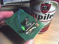 Michai 013 board and beer.jpg 640 × 480; 66 KB
 Michai 013 old and new board.jpg 640 × 480; 68 KB
 Michai 014 ain.jpg 1,684 × 1,190; 39 KB
 Michai 014 auxsel.jpg 1,684 × 1,190; 75 KB
 Michai 014 ctrsel.jpg 1,684 × 1,190; 67 KB
 Michai 014 dio.jpg 1,684 × 1,190; 48 KB
 Michai 014 finished board downside.jpg 640 × 480; 54 KB
 Michai 014 finished board topside.jpg 640 × 480; 58 KB
 Michai 014 logic.jpg 1,684 × 1,190; 47 KB
 Michai 014 mcu.jpg 1,684 × 1,190; 87 KB
 Michai 014 power.jpg 1,684 × 1,190; 33 KB
 Michai 014 swap ab.jpg 1,684 × 1,190; 45 KB
 Michai 015 board.jpg 640 × 480; 70 KB
 Michai 015 bsc.jpg 448 × 212; 12 KB
 Michai 015 bscan.jpg 404 × 514; 38 KB
 Michai 015 components.jpg 640 × 480; 58 KB
 Michai 015 schem.jpg 1,684 × 1,190; 95 KB
 Michai 015 tap fsm.jpg 852 × 952; 56 KB
 Michai 015 timing.jpg 956 × 382; 33 KB
 Michai 017 action.jpg 640 × 480; 68 KB
 Michai 017 big bush back.jpg 640 × 480; 58 KB
 Michai 017 big bush front.jpg 640 × 480; 54 KB
 Michai 017 board.jpg 640 × 480; 53 KB
 Michai 017 coke.jpg 640 × 480; 69 KB
 Michai 017 miffy.jpg 640 × 480; 69 KB
 Michai 017 real bunnies.jpg 640 × 480; 70 KB
 Michai 017 small bush back.jpg 640 × 480; 75 KB
 Michai 017 small bush front.jpg 640 × 480; 69 KB
 Michai 017 snug fit.jpg 640 × 480; 61 KB
 Michai 024 15kHz pulses and zapper response.jpg 640 × 480; 67 KB
 Michai 024 LED brightness.jpg 640 × 480; 53 KB
 Michai 024 alternating durations.png 640 × 400; 9 KB
 Michai 024 duckhunt.jpg 452 × 600; 50 KB
 Michai 024 pattern 5 on 1 off.jpg 640 × 480; 67 KB
 Michai 024 schematics.png 800 × 600; 6 KB
 Michai 024 target 1st attempt.jpg 640 × 480; 51 KB
 Michai 024 target 2nd attempt 4 LEDs.jpg 640 × 480; 66 KB
 Michai 024 target 3rd attempt jumpered.jpg 640 × 480; 70 KB
 Michai 024 target 4th attempt pushbutton.jpg 640 × 480; 69 KB
 Michai 024 zapper well aligned.jpg 640 × 480; 57 KB
 Michai 024 zapper with wires.jpg 640 × 480; 75 KB
 Michai 025 breadboard setup.jpg 640 × 480; 69 KB
 Michai 025 breadboard setup cover off.jpg 640 × 480; 57 KB
 Michai 025 leds resistors connected.jpg 640 × 480; 66 KB
 Michai 025 leds soldered to shaped wire.jpg 640 × 480; 66 KB
 Michai 025 modded PCB top.jpg 640 × 480; 73 KB
 Michai 025 modded PCB with MCU bottom.jpg 640 × 480; 65 KB
 Michai 025 original PCB bottom.jpg 640 × 480; 53 KB
 Michai 025 original light innards.jpg 640 × 480; 67 KB
 Michai 025 result.jpg 640 × 480; 75 KB
 Michai 025 sine and spike.jpg 553 × 194; 14 KB
 Michai 025 uploading.jpg 640 × 480; 64 KB
 Michai 031 back.jpg 640 × 480; 59 KB
 Michai 031 claxon.jpg 640 × 480; 68 KB
 Michai 031 claxon power.png 320 × 234; 8 KB
 Michai 031 first board.jpg 640 × 480; 69 KB
 Michai 031 front.jpg 640 × 480; 54 KB
 Michai 031 innards.jpg 640 × 480; 71 KB
 Michai 031 schem nok 1.jpg 682 × 392; 25 KB
 Michai 031 schem nok 2.jpg 578 × 221; 12 KB
 Michai 031 schem ok.jpg 535 × 259; 13 KB
 Michai 031 serial dongle.jpg 640 × 480; 67 KB
 Michai 032 board antenna led.jpg 640 × 480; 58 KB
 Michai 032 discharge.png 320 × 234; 6 KB
 Michai 032 failed T2 annotated.png 320 × 234; 8 KB
 Michai 032 flame ramp.png 640 × 400; 9 KB
 Michai 032 inserting into lamp.jpg 640 × 480; 55 KB
 Michai 032 lamp in action.jpg 640 × 480; 70 KB
 Michai 032 led nest diffused on table.jpg 640 × 480; 74 KB
 Michai 032 led nest lit.jpg 640 × 480; 74 KB
 Michai 032 led nest unlit.jpg 640 × 480; 65 KB
 Michai 032 lighter modified.jpg 640 × 480; 75 KB
 Michai 032 lighter original.jpg 640 × 480; 74 KB
 Michai 032 near linear charge.png 320 × 234; 5 KB
 Michai 032 schem.png 800 × 600; 7 KB
 Michai 032 spark on reset.png 320 × 234; 5 KB
 Michai 032 spark on reset zoomed.png 320 × 234; 6 KB
 Michai 042 action.jpg 1,824 × 1,368; 1.49 MB
 Michai 042 frames.png 320 × 234; 4 KB
 Michai 042 nasty0.png 320 × 234; 3 KB
 Michai 042 nasty1.png 320 × 234; 3 KB
 Michai 042 nasty2.png 320 × 234; 3 KB
 Michai cbapainting action.jpg 640 × 480; 74 KB
 Michai cbapainting prereq.jpg 640 × 480; 61 KB
 Michai cbapainting sponge.jpg 640 × 480; 69 KB
 Michai hd platter.jpg 640 × 480; 56 KB
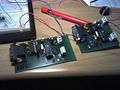
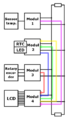
 Modules.jpg 1,024 × 768; 291 KB
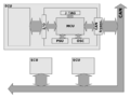
 Moduly.jpg 1,024 × 768; 260 KB
 Napoleon-1.jpg 264 × 423; 42 KB
 Noninverting bias.png 655 × 336; 109 KB
 Ohm.jpg 640 × 480; 53 KB
 OldCDROMdrive.JPG 3,648 × 2,736; 3.72 MB
 OldCDROMdriveSeal.JPG 2,816 × 2,112; 1.59 MB
 Opabias.pdf ; 847 KB
 Opabias inverting.jpg 641 × 287; 30 KB
 P104 breadboard.jpg 640 × 360; 101 KB
 P104 schem.png 662 × 231; 159 KB
 P104 scope.jpg 640 × 360; 121 KB
 PPM Wall clock.jpg 714 × 770; 129 KB
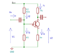 Pe1 bjt ce.png 685 × 627; 7 KB
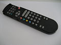 Philips remote control.jpg 704 × 528; 34 KB
 PitCANapp1.JPG 900 × 600; 162 KB
 PitCANapp2.JPG 900 × 600; 141 KB
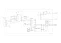
 PitCANdiagram.png 423 × 739; 26 KB
 PitCANidea bw.png 1,296 × 974; 43 KB
 PitCANjtag-dev.jpg 900 × 600; 91 KB
 PitCANjtag-layout.png 961 × 518; 29 KB
 PitCANjtag-schem.png 2,116 × 1,335; 32 KB
 PitCANpcb-can-layout.png 812 × 762; 40 KB
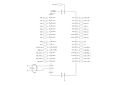
 PitCANsch can.png 592 × 420; 5 KB
 PitCANsch cpu.png 1,263 × 1,270; 33 KB
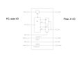
 PitCANsch io.png 435 × 424; 5 KB
 PitCANsch jtag.png 695 × 536; 7 KB
 PitCANsch psu.png 1,228 × 420; 10 KB
 Pit 2016-03-07 raspi home-PCB-scan.jpeg 999 × 915; 269 KB
 Pit 2016-03-07 raspi home-schematic.jpeg 2,338 × 1,653; 372 KB
 Pit BOL IMG 2411.JPG 1,200 × 800; 86 KB
 Pit BOL IMG 2414.JPG 1,200 × 800; 141 KB
 Pit BOL IMG 2657 h962.jpg 640 × 962; 216 KB
 Pit BOL IMG 2659 h960.jpg 639 × 960; 199 KB
 Pit BOL IMG 2660 h960.jpg 639 × 960; 201 KB
 Pit BOL IMG 2671.jpg 1,200 × 798; 157 KB
 Pit BOL IMG 2672.jpg 1,200 × 798; 174 KB
 Pit BOL IMG 2673.jpg 798 × 1,200; 146 KB
 Pit BOL IMG 2674.jpg 798 × 1,200; 150 KB
 Pit BOL IMG 2676.jpg 1,200 × 798; 184 KB
 Pit BOL IMG 2677.jpg 1,200 × 798; 134 KB
 Pit BOL IMG 2678.jpg 798 × 1,200; 105 KB
 Pit BOL IMG 2679.jpg 798 × 1,200; 124 KB
 Pit BOL IMG 3189a h960.jpg 924 × 960; 135 KB
 Pit BOL IMG 3190a h960.jpg 818 × 960; 127 KB
 Pit BOL IMG 3191a h960.jpg 818 × 960; 131 KB
 Pit BOL IMG 3192a w960.jpg 960 × 747; 124 KB
 Pit BOL IMG 3193a w960.jpg 960 × 761; 122 KB
 Pit BOL f1 sch1.png 1,545 × 2,295; 39 KB
 Pit BOL f2 pcb top.png 636 × 637; 81 KB
 Pit BOL f3 IMG 2681.jpg 1,200 × 798; 137 KB
 Pit BOL pcb scan.jpg 719 × 720; 100 KB
 Pit RaspiHomeTest.jpeg 2,136 × 1,424; 925 KB
 Pit almost screen 1.jpg 1,068 × 712; 150 KB
 Pit almost screen 10.jpg 768 × 1,024; 188 KB
 Pit almost screen 11.jpg 1,024 × 768; 205 KB
 Pit almost screen 12.jpg 768 × 1,024; 208 KB
 Pit almost screen 15.jpg 768 × 1,024; 180 KB
 Pit almost screen 16.jpg 768 × 1,024; 187 KB


