Difference between revisions of "Intelligent xmas decoration"
| Line 138: | Line 138: | ||
wiki.productivity *= 10000; | wiki.productivity *= 10000; | ||
</blockquote> | </blockquote> | ||
| + | |||
| + | But of course: | ||
| + | |||
| + | <pre> | ||
| + | < pit> one shall remove batteries BEFORE he lies down a device that would be unused for long period of time | ||
| + | < pit> you note this down | ||
| + | <@michai> I note this down at once. | ||
| + | </pre> | ||
| + | |||
| + | (please note, I have OPS, and young Pit does not.) | ||
---- | ---- | ||
Have fun -- [[User:Michai|Michai]] | Have fun -- [[User:Michai|Michai]] | ||
Latest revision as of 21:22, 15 December 2012
Contents
Introduction
Fact: LEDs are nice, PWM is nice, and coin-cell batteries are cheap (1 EUR for 6x LR44). Last year, I wanted to make an xmas-decoration using many small 'xmas star' type lights, where LEDs of different colour were PWM'd in a random pattern. Sadly, the CBA prevented that.
The idea then was to use two 1.5 V coin-cell batteries pressed against each other, a piece of veroboard, and a PDIP-8 MCU. Since then, I have been enlightened, and have started to use proper layouts for stuff like this.
General operation
In short, the device toggles between sleep- and run-mode depending on changes in ambient light. In particular, it responds to 'light turned on' and 'light turned off' events, defined as changes in light-intensity above a certain magnitude within a certain time.
From the moment the battery is inserted, the device would do the following:
- wake up every second using watchdog timeout, and measure ambient light intensity
- if a well-timed 'light off' / 'light on' / 'light off' sequence is seen, enter run-mode, else go back to sleep
- in run-mode, PWM the LEDs on/off in random pattern until ambient light intensity rises more than a certain threshold, then go back to sleep
In addition, while in sleep-mode, the battery-voltage is periodically checked; if it drops below a threshold (0.9 V - this is about the minimum for the boost-converter to make 3.3 V out of), blink the red LED every second.
Hardware
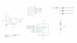
(See fig.1 for schematic.)
Power-source
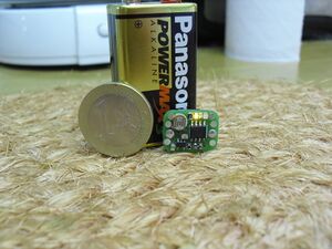
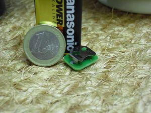
To save size and experiment with new stuff, instead of 2 coin-cells to make 3 V (enough to drive a LED and feed a >1.8 V MCU), a DC/DC-converter was used. I chose the TI TPS61097-33DBVT (datasheet at Farnell) boost-converter, which has a quiescent current of about 10 uA, and can deliver 3.3 V from an input ranging from at least 0.9 V to 5.5 V.
The datasheet suggests two 10 uF caps and one 10 uH inductor as external components, so let's do that as well. I fried at least 1 inductor in the process. This thing just worked, and worked very nicely, I was impressed.
Measuring light-intensity
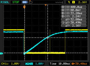
Ambient light intensity is measured using a constant voltage (Vcc) charging a cap through an LDR, and measuring the time it takes to charge to a certain voltage. As LDR-resistance decreases with light-intensity, shorter charge-times indicate brighter ambient-light. The cap is used instead of a resistor voltage-divider to minimise current.
Measurements are taken periodically, using the following sequence:
- drain the cap by discharging it through a MCU-pin
- let it charge through the LDR, and measure charged voltage about every millisecond (arbitrary time)
- if 3 consecutive samples indicate > 2/3 Vcc (2.2 V), measurement is complete
- total measurement-time from draining to charging the cap is converted to a percentage of 'darkness'.
In fig.4, the yellow low-time to the left of the spike is N * (1 ms + sampletime), and the low-time to the right of the spike is N * 1 ms, just indicated for debugging (i.e. to read the actually calculated percentage). The delay between the 2nd cursor and the spike is the verification that 3 consecutive samples indeed read > 2/3 Vcc.
The kind people on #electronics mentioned it was probably not such a bright idea to discharge the cap without resistor through an I/O pin, and that's true, but let it be a wise lesson for the next time, and let it Be So.
Resistance of an LDR probably doesn't vary linear with light-intensity, and what's more, I don't know whether what my eye percieves as 'twice as bright' is actually twice the intensity anyway. I simply chose the 0..100% scale to be somewhat sane:
<syntaxhighlight lang="c">
 //   TL-lit hobbyroom, uncovered             :  <5
 //   TL-lit hobbyroom, hand 10cm over LDR    :   13
 //   TL-lit hobbyroom, hand 1cm over LDR     :   75
 //   2nd light hobbyroom, uncovered          :   18
 //   2nd light hobbyroom, hand 10cm over LDR :   80
 //   2nd light hobbyroom, hand 1cm over LDR  : >100
</syntaxhighlight>
('hobbyroom' is some arbitrary room, 'TL' is fluorescent tube light, and '2nd light' is some halogen light further away)
MCU
The trustful ATtiny13 (1 kb flash, 63 bytes RAM if I'm not mistaken) would be more than enough for this. In the future, perhaps ATtiny22 or similar, or PIC10f200 (both SOT23) are nice for such stuff.
Clock is selected to be internal 128 kHz resonator for minimum power-consumption. While not active, power-down mode is entered, to be woken up by (dummy) watchdog timeout interrupt each second. Power-down mode consumes about 6 uA; active mode about 200 uA (which is much less than an active LED, which is in the > 2 mA range).
Software
The software is implemented using a classic 'main loop' and 2 coroutines, inspired by Adam Dunkels' Contiki coroutines. Main loop is as follows:
<syntaxhighlight lang="c"> for ( ;; ) {
power_down_1s();
 TASK_monitor_darkness( &enable );
 if ( enable ) {
   TASK_pwm_leds();
 }
 else {
   if ( !batt_is_ok() ) {
     blink_red( 1, 0 );
   }
 }
} </syntaxhighlight>
In words: an 'enable' flag is set/cleared from 'TASK_monitor_darkness', and indicates whether to display the xmas-effect or not. Another task does the actual xmas-effect ('TASK_pwm_leds'). These 'tasks' each implement a state-machine using coroutines.
In short, a coroutine is a procedure that can be re-entered at a previous exit-point. Some ways to implement them are generic C 'switch'-constructs with a static variable indicating the label to jump to, or GCC 'labels as values' C-extension, where you can dereference a label. I chose the latter, because it produces smaller code. See the C header for definition and example.
The PWM-task is simple, and basically reads EEPROM values, 4 bits at a time, and selects LED to use - or none - for this iteration (2 bits), and delay between 2 PWM-ramps (2 bits). Each device is programmed with unique randomness-data.
Ambient-light monitoring task
The monitor-task keeps track of ambient intensity percentage history (current intensity, intensity of last measurement, and intensity of measurement before that), and continuously verifies it against a valid start-sequence for the xmas-show.
We are mainly interested in 'light goes on' and 'light goes off' events. These are defined as follows:
- light goes off == darkness_percent[ N ] - darkness_percent[ N - 2 ] > threshold
- light goes on == darkness_percent[ N ] - darkness_percent[ N - 2 ] < -threshold
(index being the number of the measurement, i.e. once every second)
Furthermore, 'light is stable' is defined as absence of either event.
Comparing darkness_percent[ N ] to darkness_percent[ N - 1 ] instead of [ N - 2 ] does not work in border-cases where the light goes off/on exactly during a measurement - an event could go by unnoticed. 'Threshold' is determined experimentally (and is 20).
After a 'light goes on' or 'light goes off' event, one additional measurement is skipped to deal with border-cases where light goes off (or on) exactly in the middle of a measurement, and the total increase (or decrease) in ambient darkness is > 2 * threshold. If this delay wasn't there, the sequence could be broken because an additional unexpected 'light goes off' (or 'on') event would be seen, after which sleep-mode would be re-entered.
When in sleep-mode, run-mode is entered if and only if:
- light goes off
- light stays off (or at least stable) for 1 to 3 seconds
- light goes on
- light stays on (or at least stable) for 1 to 3 seconds
- light goes off
When run-mode is entered, the darkness-percentage of that moment is latched. Run-mode is canceled when a measured darkness-percent is at least 'threshold' lower than the latched value.
Demo!
Description from the youtube-site:
ATtiny13 @ 128 kHz, DC/DC converter, LR44 battery, LDR and 3 LEDs. Operation is as follows (shown in the video in this order): turn off the light; if light stays off for longer than 3 seconds, go back to idle mode. If light stays off for 1 to 3 seconds, then goes on again for 1 to 3 seconds, then goes off permanently, LEDs start to PWM on and off, from randomness-table in EEPROM (until the light goes on again). At all times, the light-intensity is measured about every second, and fed into state-machine controlling operation. When idle, a battery-check blinks the red LED every second if battery-voltage drops below 0.9V, which is about the minimum the DC/DC-converter can still turn into 3.3V. Power-consumption when sleeping is about 16 uA (6 for the MCU, and 10 for the DC/DC-converter).
<youtube size="small" align="right">QRNnnUKaacs</youtube>
UPDATE! UPDATE! UPDATE!!!
20121215 - I plopped in new batteries, after removing the old ones (which had started leaking), removing corrosion + solder on contact pad, and applying new solder.
wiki.productivity *= 10000;
But of course:
< pit> one shall remove batteries BEFORE he lies down a device that would be unused for long period of time
< pit> you note this down
<@michai> I note this down at once.
(please note, I have OPS, and young Pit does not.)
Have fun -- Michai
