Difference between revisions of "8-way temperature sensor"
(Created page with "__NOEDITSECTION__ category:projects done [[image:xmas_sch.png|thumb|'''Fig.1: schematics.''' A boost-converter generates 3.3 V for the MCU (V_OUT), LED-currents are sinked (...") |
|||
| Line 2: | Line 2: | ||
[[category:projects done]] | [[category:projects done]] | ||
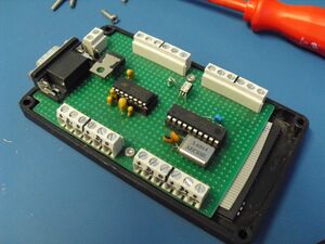
| − | [[image: | + | [[image:038 innards.jpg|thumb|'''Fig.1: innards.''' Not very impressive: a MCU and a RS232 transceiver, and that's basically it.]] |
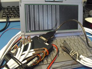
| − | [[image: | + | [[image:038 reading_data.jpg|thumb|'''Fig.2: reading data using PC.''' Box spits out a line of values each second or so, one value for each sensor, with indications of data- or parity-error, or missing sensor.]] |
== Introduction == | == Introduction == | ||
| − | + | For work I built a small temperature-sensor box, with 8 TSIC506 sensors - very accurate (about +/-0.1 degC) and digital. | |
| − | + | Although this thing was used (once), it's not very useful for higher temperatures, since sensors have max readout at 60 degC. Then again, sensors were my own, and I just plopped them in there because they were collecting dust here. | |
| − | + | == Hardware == | |
| + | |||
| + | The sensor has 3 pins: gnd, Vcc and data. When powered on, it starts spitting out 12-bit values every second or so. For each data-byte, a 10-bit frame is used: a start-bit, used to indicate start-of-byte, and to allow the receiver to measure 1/2 of the bittime, which is used to sample subsequent bits. After 8 bits of data comes a parity-bit. Everything is nicely explained in datasheets I am currently too lazy to dig up. | ||
| + | |||
| + | All sensors share a Vcc, directly supplied one of the MCU's I/O pins, while each sensor has a dedicated MCU I/O-pin for data. | ||
| + | |||
| + | == Software == | ||
| + | |||
| + | [http://mircad.com/038___c.c.txt The software] is too simple to discuss; main loop is as follows: | ||
| + | # sleep | ||
| + | # power-on all sensors (shared Vcc) | ||
| + | # read value from sensor #1 (ignore the rest) | ||
| + | # validate and format value, and send to host through UART | ||
| + | # power off all sensors | ||
| + | # power on all sensors | ||
| + | # read value from sensor #2 | ||
| + | # power off all sensors | ||
| + | # ... | ||
| + | # redo from start | ||
| + | |||
| + | User can read each sensor's temperature using a terminal-emulator or script; basic error-checking is done so that parity-/communication-errors and 'missing sensor' issues are indicated as well. That's all! | ||
---- | ---- | ||
Have fun -- [[User:Michai|Michai]] | Have fun -- [[User:Michai|Michai]] | ||
Revision as of 18:21, 3 July 2011
Introduction
For work I built a small temperature-sensor box, with 8 TSIC506 sensors - very accurate (about +/-0.1 degC) and digital.
Although this thing was used (once), it's not very useful for higher temperatures, since sensors have max readout at 60 degC. Then again, sensors were my own, and I just plopped them in there because they were collecting dust here.
Hardware
The sensor has 3 pins: gnd, Vcc and data. When powered on, it starts spitting out 12-bit values every second or so. For each data-byte, a 10-bit frame is used: a start-bit, used to indicate start-of-byte, and to allow the receiver to measure 1/2 of the bittime, which is used to sample subsequent bits. After 8 bits of data comes a parity-bit. Everything is nicely explained in datasheets I am currently too lazy to dig up.
All sensors share a Vcc, directly supplied one of the MCU's I/O pins, while each sensor has a dedicated MCU I/O-pin for data.
Software
The software is too simple to discuss; main loop is as follows:
- sleep
- power-on all sensors (shared Vcc)
- read value from sensor #1 (ignore the rest)
- validate and format value, and send to host through UART
- power off all sensors
- power on all sensors
- read value from sensor #2
- power off all sensors
- ...
- redo from start
User can read each sensor's temperature using a terminal-emulator or script; basic error-checking is done so that parity-/communication-errors and 'missing sensor' issues are indicated as well. That's all!
Have fun -- Michai

