Difference between revisions of "8-way temperature sensor"

From Electriki
Jump to navigationJump to search
(Created page with "__NOEDITSECTION__ category:projects done [[image:xmas_sch.png|thumb|'''Fig.1: schematics.''' A boost-converter generates 3.3 V for the MCU (V_OUT), LED-currents are sinked (...")
(No difference)

Revision as of 17:49, 3 July 2011


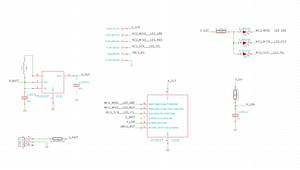
Fig.1: schematics. A boost-converter generates 3.3 V for the MCU (V_OUT), LED-currents are sinked (sunk?) by the MCU using a shared series-resistor, and light-intensity is obtained by measuring how long it takes to charge a cap (V_LDR).
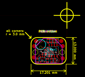
Fig.2: PCB-layout, as seen in Kicad. Red traces are on the front; the back only has a battery-holder. The blue circle on the upper left is the LDR; the big IC is the MCU, and the SOT23-5 is the DC/DC converter. The 3 pads on either side are ISP-signals for programming and debugging.

Introduction

bla

General operation

etc


Have fun -- Michai