Wobbly bike light
Contents
What is this?
Recently I got stopped by the friendly police because I didn't have any light on my bike. Got away with a warning (because either my rap is very smooth or the police-force is essentially a toothless lion), but ok, perhaps it would indeed be a good idea to be seen by other traffic.
They sell very cheap LED bike-lights everywhere; mostly it's 3 LEDs, blinking, still, or off, selectable by a pushbutton. Newer models are just too small to tinker with, so the idea was to get a nice big old one and modify that into something less mainstream.
Hardware
Although the software is what makes this work, the soldering, fitting, and thinking about physical layout was also interesting and fulfilling, if it may be called that.
Original bike-light
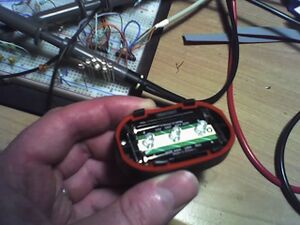
Got a front-/backlight set for a few EUR; nice to have 2, in case I fsck one up :-). Opening up the front light (fig.1) reveals 2 AAA batteries on either side of a small PCB. Some reflective thingie was also there; after tossing it away there was plenty of room under the cover.
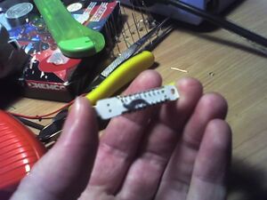
The PCB (fig.2) had a pushbutton contact-pad on one side, and power-terminals on the other. Desoldered the LEDs, scraped all copper tracks off it except some small 'soldering-pads' near the end, made it a bit thinner in the middle so that it would fit between the pins of a DIL chip, and that was basically it.
MCU and pin-layout
The MCU of choice here - isn't it always - would be the Atmel ATtiny2313; it has 20 pins, of which 2 are Vcc/gnd, 1 is reset (let's just leave it enabled, it's easier), leaves 17. Just enough for 16 LEDs and a pushbutton to turn the device on/off. Naturally a thing like this doesn't need exact timing, so internal 8MHz RC-oscillator would do fine, saving 2 pins.
There is no schematics here, because it's all very very simple: 16 pins would each drive a LED through a 2k2 series-resistor, while 1 pin would be externally pulled up (100k to Vcc), and pushbutton would pull it to ground. I used pins PA0, PA1, PB0..7 an PD0, PD1 and PD3..6 for LEDs, and PD2 (INT0 external interrupt pin) for the pushbutton.
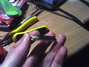
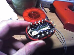
Result of soldering MCU onto the PCB can be seen in fig.6 (bottom) and fig.7 (top). So, the MCU itself will not be visible when PCB is mounted again - only the LED-pins will be accessible.
LEDs
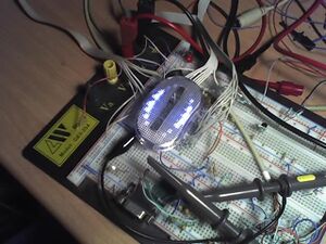
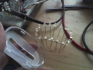
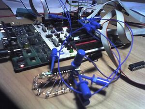
The breadboard-setup (fig.3 and (fig.4) showed that the spacing between LEDs attributed a lot to a nice animation, so I used a 'ring' of wire shaped to fit inside the translucent cover to solder LEDs onto (fig.8).
After mounting the PCB inside the battery-less light again, each LED's anode was soldered to one of the MCU's LED-pins through a 2k2 resistor (fig.9). It's so much easier to 'nicely' map pins into a continuous sequence from software than fscking about with crossed wires :-)
Software
It's funny how it works, at least with me; some totally unrelated (or is it!) event brings you to read something, then read something more, then something related, then something only slightly related, which is then used for hobby-crap.
Binary code modulation
In this case, the 'unrelated event' was reading how to avoid interrupt jitter in the amazing TellyMate device, and the 'only slightly related' stuff was Binary Code Modulation ('BCM' hereafter).
This is an alternative to using multiple software-PWM's in parallel, when a big(ger) number of channels is required. For each channel, the idea is to output each bit in the modulator-setpoint (0..100%, or 0..255 in my case) for a period corresponding to the weight of that bit. In other words, bit 0 (LSB) is output for a period T, bit 1 is output for a period 2T, bit 2 for a period 4T, etc.
The smart part is that, for a set of, say, 8-bit BCM channels, a single timer-interrupt can set precalculated bit-values for a number of channels simultaneously. For more info about the precalculation and code-snippets, just look at the explanation if you want.
The 16 LED-pins are spread over 3 output-ports. Therefore, in each BCM timer-interrupt, 3 PORT-values have to be written (and that's basically it - really, it's so much nicer than using software-PWM for this kind of stuff). Now all LEDs can be controlled individually. I use a 'CreateLEDSequence()' function to calculate raw PORT-values from an array of 8-bit LED intensities for each LED.
Now each LED can be individually set to intensity 0..255. Neat. The BCM I use has a 244 Hz period (8MHz oscillator frequency, 1:64 timer prescaler, 512 timer ticks in a period).
Light spike and perceived intensity
When ramping a LED's 'on-time' from 0 to 255, it can be seen that the perceived intensity is not linear with the on-time; differences in the low-range (near 0) are much more clear than differences in the high-range (near 255). I think gamma-correction corrects for this (but no need to correct me if I'm wrong, since I don't really care too much anyway).
Regardless of whether corrected for or not, at the end of the day, difference between on-time of '0' and '1' is still clearly visible. This is not nice. However, difference between on-time '1' and '2' (i.e. 1/255 and 2/255 of the time) is already much less visible. Therefore, to fix this, each LED always has an on-time of at least '1'.
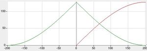
As a sad attempt at poor man's gamma-correction, I use a 'spike'-shaped ramp from on-time 0 to 255, as can be seen in the green-line in fig.5. This is simply calculated from the sine-table as spike_val( x ) = ( AMPLITUDE - abs( sine_val( x ) ) ) for some range of values. 2 of these 'spikes of light' will move around the 16-LED circle.
Fixed-period sine-calculation
After searching for a bit about how to approximate sine-values using fixed-point arithmetic, I decided to use a variant of the midpoint circle-drawing algorithm (which is very smart BTW), and later decided to ditch that as well, in favour of a simple lookup-table in flash-memory. An ATtiny2313 has 2k flash, and since code would not take too much space, who cares.
In the table, for a sine with amplitude 127, I store 1/4 of a sine-period (fig.5, red line) in a 201-byte long array of samples; all sine-values can be calculated from that. Why 201? Because then, difference between 2 subsequent values is at most 1, i.e. there are no 'gaps'. This is not a problem when using values directly from the table, but it will be a problem when using longer sine-periods (see below). A full sine-period thus corresponds to 804 samples.
Longer sine-periods
Leds moving about in a single fixed-period sine swing are very uninteresting, as we all know from the Golden Age of C64 demo-programming when I was 15 and the monthly trips to Venlo computer-meeting were all we lived for and disks were expensive and and...
And this one time, at band camp, ...
Anyway. Using Bresenham's line-drawing algorithm, 'angle'-values for a longer sine wave can be mapped onto the angle-range (0..200) of the fixed-period sine from the lookup-table. I found there are a lot of crappy sites explaining (or not explaining) this algorithm; if interested, this explanation was one that I liked.
Lookup-table and longer-period sine generation can be found in sin.c. Modulo-operator can be a heavy bastard for this MCU, but ok, no need for fast code here, so why not.
A nice, not-too-boring wobbly position for a 'spike of light' on the 16-LED circle can be obtained by superimposing sine-waves of different periods onto each other, and taking the result modulo circle-path length. I use 4 such sines with periods varying from around 800 to 1400, and a circle-path length of 1024 (or, 64 'circle-points' between each LED). Furthermore, I use 2 'spikes of light' starting at opposite halves of the circle-path, moving very slowly clockwise (or counter-clockwise?) along the circle, in addition to the sine-wobble described above.
I hope this makes sense at least a bit - have a peek at the code if you want. Don't bug me with details please, I know it's not the prettiest.
Modes of operation
Operation is very simple; after connecting it to the batteries, the device enters power-down sleep mode, and wakes on INT0 external level-interrupt from a press on the pushbutton. Another push on the button puts it back to power-down sleep.
Between each timer-interrupt, the device sleeps in idle-mode to further reduce power-consumption. One nice thing about not actually powering off anything, is that the LED-effect can continues where it left off a week ago. Nice.
Result
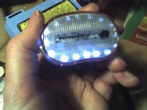
Final result can be seen in fig.10, and a video can be seen below. Now I have a nice story to tell when the police stops me another time - which would be never. :-)
<youtube size="small" align="right">nx-5H8p4s0g</youtube>
Have fun -- Michai
