How Cutie manages my measurements

Or rather: how does a QT based application acquire measured data, display it and export it into database for further analysis.
What does this do?
Long story short:

How does it work?
It's a chain built of few links. The above graph (simple as it is) describes whole procedure quite good. I'll start the detailed description from the QT application, as it more or less manages whole operation.
The cutie app.
A simple application is running on my PC. It uses QT library with additional serial interface module (Abstract Serial) and MySQL database driver module (QtSql/QMYSQLDriver). Figure 1 shows the application window. Main part of it are two displayed temperature values measured inside my room, and outside, on my balcony. Below are three buttons: the temperature button, the database button and the serial link button. The icons are also serving the role of status controls for the whole app: background colour tells the user what's going on at the moment: red means an error, yellow means action taking place and green one means all is tip-top good.
The temperature button.
One can request a measurement with this button. Once pressed, changes its background colour to yellow and sends a measurement request to the MCU module. When module replies with data, it updates the displayed values and turns the background colour back to green. I call this measurement a "quick" one. It isn't stored anywhere, just displayed on my desktop.
The database button.
Clicking this one also causes it flip to yellow. Then a measurement read request is sent to the MCU module. The reply causes the application to fetch a SQL query with the acquired data and upload it to a remote MySQL database. If there's any error with that - the button's background is being changed to red. If there's no errors and the SQL query is properly executed, the QT application sends a confirmation frame to the MCU board, telling it that this measurement has been stored properly. Then the MCU looks for another unsent data and the procedure is repeated till all of the data in the database is up to date. Of course the MCU module informs the reader application of such fact with a specific command, telling it to set the button's background to green again. A "quick" temperature measurement is performed at this point, to update the application's display.
The serial link button.
Pressing this button causes the application to re-initialize the serial link. This button is called automaticaly on the reader application's startup. Then the transmission parametters are set and the application tries to use the communication port. If an error occurs (i.e. port is already used), button's background turns red. If the connection is made, the application sends current datetime stamp to the module. Then it automaticaly presses the database button.
The MCU module.
Power supply and continous operation.
I've used one of the universal can modules for this project. It requires 4.5VDC minimum voltage supply to work completely, and even about 3.5VDC will let it work without the CAN transceiver operational. This allows me to easily keep it ON all the time, by just adding a set of three AA cells and two schottky junctions to it. By default it is powered from my PC's USB 5VDC supply. The (lower) battery voltage source is then cut-off by the schottky diode. The USB sources supply even while being in standby mode. But if it is turned off, the main voltage drops below about 4.6VDC, and then the batteries source the device. As soon as the 5VDC shows back at the USB port, it once again cuts the batteries off and becomes the voltage source. This allows continous operation. The RTC can be only once set with the true datastamp information and then continue to work supposingly forever. :-)
Temperatures measurement.
I have two DS18B20 sensors attached to this MCU board. One of them is in my room, measuring the indoor temperature. The other one is outside, on my balcony, in the almost a stevenson screen box that I've built some time ago. The module is programmed to respond with a quick measurement's values to just update the display. Although, the main operation is to perform scheduled measurements. This data will be used to draw a temperature VS time graph later on. When starting up the module, it falls into a "do nothing" loop. The client application running on the PC sets the real datetime in the internal RTC, and then the application begins collecting data.
Managing data collection.
It is not a problem to send the measured data when I have the PC turned on. I began to wonder how would I prevent this device from losing values measured when the PC is turned off. Or when I simply have no internet connection available due to some technical difficulties. Answer is easy: store it in the MCU's internal memory. Luckily, the STR712 happens to have a whole 16kB flash memory bank, that I am not (yet) using. I write my application data into the 256kB bank0, so the 16kB bank1 is waiting for me to store my data in it. One can write 32 bits long data writes to the memory, which is exactly what I need to store two sensors' measurements. I'm also storing the datestamp and some other meta data in another 32 bits, so a single complete mesurement takes 64 bits (8 bytes) in the flash. This leaves me with possibility to store 2048 measurements. Measuring every 15 minutes, the module could stay offline even for 3 weeks and 8 hours. Me gusta!
Having the whole flash memory in bank1 arranged in 8B blocks, the application reffers to every measurement by an index value (0-2047). After uploading a measurement's value to the database successfully, the client application can return the index value to the MCU. Now the measurement is marked as "already sent". This prevents from uploading the same measurement twice. Some simple mechanisms are responsible for finding an unused cell in the flash memory, to write next measurement's values, too. Also the whole bank is split into two sectors, 8kB each. I can erase sector 0 when writing last cell in sector 1 and vice versa.
Note: Of course the maximum offline period varies depending on what number of measurements has been already stored. This is caused by the fact that one has to erase whole sector (8kB) of flash at a time. In worse case scenario, when putting module offline while it's at index 1047, it can only write indexes 1047-2027. This is still 10 days and 16h of operation w/o losing any data though.
The charts generator.
Aim is to have a huge amount of data to work with and huge ammounts of data are best managed by databases. MySQL is what everybody knows. Simple, popular, reliable, free of charge. The QT application I wrote for this project uploads measured data to a remote server. On the same server I have a PHP based page running: http://pit.cba.si/temperatures. Few simple SQL queries are used to get the data required by the pChart graphs drawing library (for PHP). I currently draw two graphs. First one is showing data for the last 24 hours' measurements, every 15 minutes. The second graph shows the maximum and minium values' ranges for last 31 days (temperature amplitudes per day).
Charts are automaticaly generated for every single visit on the page, however the values in the database are only updated when my PC is running. This may cause some lags sometimes, especialy since I don't keep my PC running at nights. Checking back in few hours should give updated results.
Conclusions.
First of all, why would I do this? Well a temperature sensor is a good thing to have in every house. Since I have the hardware already done, and the PC is running quite often, too... The question should be why NOT to make it.
Then there's the QT (cutie) app. Yes one doesn't need that to just simply display temperature. But as far as I remember, I wanted to learn a way to quickly develop a good looking GUI desktop/clicked application that would work with my projects. Seems like QT does just that. Nokia nowdays doesn't sound like quality, but I actualy like this one a lot! Within few minutes one can have a simple app running. Within few hours one can have an app that actualy does something. Within few days one can learn from the scratch, how to make pretty much everything a PC app could do. There are classes available for a really wide set of elements/functions already. Then one can write his own classes, too. Also worth mentioning - I've used the official QT creator IDE. Works great too IMHO. Thumbs up. To the QT, to the STR712's bank1 flash, to the whole project.
Gallery.
Few other pics, to have a look at...

Hardware during developement.
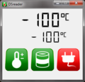
Cannot setup serial link error: Right on start, busy port. Didn't even acquire any data yet.
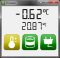
Quick measurement in progress.
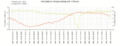
Last 24h chart for the time that i write this article.


FAILLOG
Yup. What we all love the most. "Nothing makes one happier than seeing his brother struggle" once my Analog Circuits class teacher said, before an exam failed by most of the group. Here's what happened with the application, I hope you get your doze of happiness:
2012-01 dataloss
"Let's make this app even better" was my thought when I have been playing with the database one day of the cold january of 2012. I remember my joy after discovering the "IGNORE" mysql instruction for easier altering table. Who would want to waste time playing with errors! Also this task was so easy, that making a DB backup would be waste of time as well. Few miliseconds later my joy has been substituted with regret. About two weeks of measurements have been lost from the database. Learn by mistakes, ok. No biggie. Also, I've managed to recover the data by adding "dump all flash memory via UART" feature to the firmware. All remains cool!
2012-02-11 corrupted measurements
I've removed the original paragraph, as it was not true anyways. Now about the failure: I first thought that there might have been a problem with the relay attached to the PC. Idea was that its switching noises were causing the measurement module to freeze. I did some measuring and I figured out that when unplugged from PC, the RS232 cable becomes a quite decent antenna. Yeah, the cable was hanging loose, unterminated. Crosstalks, noises, you name it... I thought that maybe all this together causes some hardware to freeze, but it was actually a software issue: I somehow forgot to keep the track of incoming chars buffer for the UART receiving routines queue. So crosstalks on the RX line were filling up the buffer array till it was overloaded. Then it altered some other parts of the code... Well it was a rookie's mistake. C handbooks advice starters to pay attention to this one, dunno why I managed to skip it. Anyhow, additional line of code was a remedy here. The firmware now keeps the buffersize within its preset boundaries. The system has lost some measurements but hey - best lessons are learned by mistakes.
Yours truly,
pit, 2011-12-21