Kitchen LED lighting


What is it all about?
Usually when I go to the kitchen, I don't really need any bright light. Why fire up the main light just to get a glass of juice? I think some dimmed light source could be enough in most cases when someone goes to the kitchen for a moment - just to grab something and get out quickly. Let's save some energy with an intelligent LED driver...
How does it work?
General concept
General idea for this application is to build a light driver that would turn lights on when someone enters the room. Of course it should only enable lights when it's needed - after twilight. It should also keep the lights on as long as someone is still in the room. Those requirements determine usage of two sensors: motion sensor and light sensor. In heart of it, there will be a Tiny AVR microcontroller, to trigger the light based on both sensors' measurements. Whole idea is presented on figure 1.
PIR sensor module
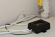
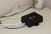
After browsing PIR sensors' offers at various suppliers it's easy to come to one conclusion: those don't come cheap. Except for actualy one supplier... Johnson&Johnson's Brise - known for their air smelling solutions. Brise's sense & spray has PIR sensor in it. Whole device with batteries and can of smell comes for around 19,00PLN (4.75EUR), while spray can itself is about 16,00PLN (4EUR, when bought separately). 19-16=3, so whole device is worth about 3,00PLN (0.75EUR). That's not expensive at all. This is cheapest sensor solution one can get. And after disasembling it there's another positive surprise inside! One just has to desolder one connector and single LED to have an easy to use 5VDC supplied PIR sensor module (PIR sensor + whole circuit needed to transform the measurement into TTL level output).
Components selection
So having the PIR sensor case handled (I've actualy had to re-wire the sensor itself and resinstall the lens for this particular app - see figure 2), let's take care of the light sensor. All it should do is to measure light's intensity in the room. Simple photo resistor will do just fine here. I will point it at the white ceiling to get a nice average measurement of how bright the light in kitchen is. This will be fed to AVR Attiny's analog input. Some while ago I've bought few totaly cheap Attiny MCUs: the attiny13a series. It has the analog input, it has interrupts bundled with GPIO, it even has a PWM timer. With 1k of flash it looks like a perfect heart of this driver. So all it's left to take care off is the figure 1's most right box: the LED. I've a handfull of N-channel IRFR2705 MOSFET's in my drawer for a while now and I like to use those in my projects. I have 2.1m long cabinets hanging in my kitchen and the light source here will be a LED stripe of the same length. The rated power usage is 4.8W/m @ 12VDC supply voltage, so I expect a 0.84A max current on the output. The IRLR2705 should handle it with its rated 0.04Ohm open channel resistance (0.028W @ R_TJA=110Cdeg/W leads to temperature of about 3 degrees over the ambient temperature w/o any radiator). Whole set of elements is fulfilled with a LM1117 5VDC LDO, BC547 NPN transistor, three resistors and three capacitors. It can be all seen on the schematic (figure 3).
The PCB
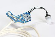
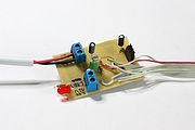
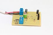
Figures 4 and 5 feature the PCB's bottom and top layers respectively. It is in fact a single layer PCB project with both SMT and THT elements installed. There is also one s/c wire on top side. Photo resistor is placed verticaly, so that it will be pointed (as mentioned before already) at the ceiling when the device lies horizontaly on the top of hanging cabinet here. Even though after some simple calculation I shouldn't be worried about the output transistor's temperature, I've decided to make use of the room inside the enclosure by enlarging the copper plane arount the transistor a bit. It is now of size being about third part of recommended (by datasheet) radiation plane for this model. If no radiator at all is enough... this is just an insurance. Better safe than sorry! I've decided not to put any programming interface connector on board to save some space - the aim is to upload the code just once and never ever look at it again. Of course, as usual, I've made the PCB myself. Laquering, lighting, developing, etching, tinning, drilling.
The enclosure
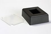
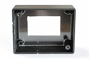
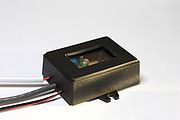
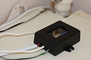
Another thing I've found in my drawer (this is not any magical furniture </btw>) is the enclosure. It's a small size universal box (H28xW59xL76 type Z70U ABS enclosure). I've managed to layout the PCB to fit it nicely. I've just needed to mod it a bit, so that the photo resistor can see the world outside the box: cutting a hole in top box' side and glueing piece of plexi glass there did the trick. I've also glued a piece of rubber pipe (aquarium type one) to hold the wires still against the box. The final look of the box can be seen on figure 6.
Installation
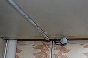
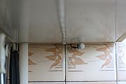
I've the driver put on top of hanging cabinets. The power supply is put right next to it. One wire goes behind the cabinets to the LED stripe under them. Another cable also goes down, to the PIR sensor module glued behind the cabinets. Only the sensor itself can be seen (with the lens cap on it). I didn't have any 230VAC socket above the cabinets, so I've pulled the mains wire from behind the stove. It's hidden behind the gas pipe, practicaly invisible. Whole installation looks acceptably discreet - hard to spot anything unusual there (in my opinion).
Software and operation
1k of flash memory is a lot for this application. When the motion sensor triggers INT0 interrupt, the microcontroller issues a light measurement with the builtin ADC. If it's dark, the light is being slowly turned on with PWM mode of the builtin timer. After lights are on, the timer is being switched into normal mode of operation and it counts time from the last motion detection. In this state every motion sensed (if it's dark at the same time...) resets the idle timer, thus prolonging the period of lights being enabled. After this period passes without any movements' notifications, the driver takes it as a "noone is in the kitchen already" and dimms the light slowly off (the timer is again in the PWM mode of operation at this stage). Of course any motion detected at this stage, causes the driver to fade lights back to being ON and whole procedure goes from the start. Simple as can be.
Other application's considerations
LED feedback?
Each and every motion sensed causes the device to measure how bright the light in kitchen is at the point. Since the photo resistor is supposed to measure average kitchen's brightness by being directed at white ceiling, won't the LED stripe emitted light interfere with the measurement? It appears not. The stripe is installed under cabinets and aims at (quite dark) work top. The sensor is placed on top of the same cabinets, so the ceiling above it (around 40cm's above cabinet's tops) remains in shade of the cabinets. It turns out i didn't even have to implement any measurement's compensation for the case when the light is already enabled and the driver is trying to decide whether or not to extend the "lights on" period.
Enter kitchen quickly
After first evening with the device installed I've noticed that it sometimes gets tricked. It turns out that when someone is quickly entering the kitchen, even though the light switch is just outside the kitchen, a person is already in (at least half step in) when the main light is being triggered on. In such cases, the driver captures movement in kitchen and triggers the LED stripe on before the main light gets switched on. Result? Both lights being enabled when all user really wants is the main light to be on. I've solved this one by adding additional light measurement just about 1 second after the initial start of fading LEDs on. The stripe isn't completely enabled at this point, and when described scenario happens, the driver dimms the LED down. Simple and working.
Power saving
After all was already working I've noticed there's still some flash space unused. What could I add to it? Well even though the device is constantly supplied with 12VDC PSU maybe I could save some power. I've hooked up the ampere-meter and it turns out that the device drains about 7.5mA of current when idling. Switching it to different power saving modes gave me measurements of 6.3mA and 5.5mA in IDLE and POWER_DOWN states respectively. The only problem with the latter one is that the device can be only waken up from it with INT0 caused by low state on corresponding GPIO. I didn't think of power saving modes when I was originaly designing the device, so there is the low state on this pin all the time when the device is idling. All I can do now is to use the IDLE power saving mode. Hey, I am still saving more than 1mA all the time! The measured 6.3mA is matching the expected datasheet values for the circuit (about 5mA drained by LM1117 and about 1.5mA drained by the Attiny). It turns out that the circuit drains 0.1mA more when it's dark. This is caused by the voltage divider built on photoresistor. Well, who would have thought of it! ;-)
Is it all good?
Yeah it is all tip-top. Family is happy about it. I am happy about it as well. The device doesn't heat up at all, it drains little of power, the LED stripe looks good, too. There are only two things to consider if one would like to upgrade this driver: the power down power saving mode and the voltage divider's values (described in more details on the end of previous paragraph). And then there's the PIR sensor in general - it senses changes of IR light falling on it. So if a person doesn't move, it doesn't know anyone's in the kitchen. So if someone's just sitting there, thinking, the light will surely go off unless the thinker doesn't wave his hand every few whiles or so... But that's just how those things work. I guess. I am happy with whole stuff, see the gallery for more pics of it.
Other images
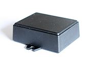
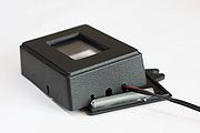
The enclosure before 'processing'.
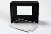
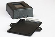
The enclosure and plexi glass piece.
The enclosure and plexi glass piece (again).
The enclosure and plexi glass piece (yet again).
The enclosure with rubber pipe glued and a piece of cable inserted to show the idea of holding wires still.
The enclosure with rubber pipe glued (again).
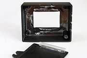
The enclosure: plexiglass piece glued in.
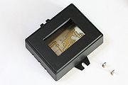
The enclosure with bare PCB inside.
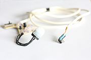
The sensor module.
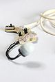
The sensor module (again).
Bottom side of the PIR module.
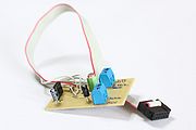
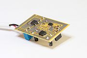
The whole device with programming tape soldered (top).
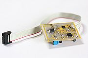
The whole device with programming tape soldered (bottom).
Whole device again. Programming tape soldered, test LED screwed in.
The completed device: PCB, bottom side.
The completed device: PCB, top side.
The completed device: PCB inside the box. On my desk.
The LED stripe and PIR sensor installed under cupboard.
The LED stripe and PIR sensor installed under cupboard (again).
The completed device. On top of hanging cabinets in my kitchen.
The completed device. On top of hanging cabinets in my kitchen (again).
The completed device. On top of hanging cabinets in my kitchen (again, again).
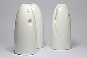
The airwicks.
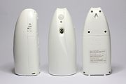
The airwicks (again).


Yours truly,
pit, 2011-08-10