DIY bike generator
Edit: This project has been shelved as I no longer ride a bike (CBA got me and I drive now). If anyone would like to take this project idea and make it a reality, please feel free to do so and expand on this page
Fed up of continually spending money on buying batteries to power the lights on my bike, I have taken up building a generator that will power the lights (and anything else if it can extract enough leg power).
Contents
Project goals
Aim: to create a generator for my bike that will give enough juice to power the lights (and perhaps a handle bar warmer if I'm lucky)
Project duration: Short (a few days work at most)
Project cost: next to nothing, everything will come from existing spare parts/salvage.
Power output: All the lights on my bike are fairly low powered LED lamps, The front being a 10-LED array drawing roughly 100mA @ 5V, and the rear about 30-40mA @ 3V. The generator will also charge a rechargeable battery to cover times when I'm sitting at traffic lights or generally not going very fast at all. The equipment requires 500mW + 90-120mW = 620mW peak, a 300mW charge to the battery should be sufficient, giving a total power requirement of just under 1W at regular speeds.
History
In the good old days, the only way you could power the lights on your bike was with a small dc dynamo that was driven by the rear wheel since batteries were the size of small family cars. They had a few disadvantages, the drive was via a rubber gear that engaged with the wheel. This of course meant moving parts and lots of wear, requiring regular maintenance to keep up the power output. The advantage of this project is there are no moving parts in addition to those a bike already has - it consists of a hub with embedded magnets fixed to the rear wheel, with a coil fixed to the bike frame, and using some seriously strong magnets salvaged from hard disks should (I repeat SHOULD) provide a fairly decent power output.
On a side note about the power output, many moons ago I decided to see what I could generate by running a stepper motor like an old dynamo directly off the rim of the back wheel, it was easily able to dimmly light a 100w light bulb, and with a little extra work (the bike was upside down and I was peddling one-handed) the bulb would go to full brightness. Unloaded I measured the output of the stepper motor at over 300V!, loaded up I measured a healthy 80W+ of electricity being generated by my wimpy arm, something which I figured was comparable to 'light/normal cycling conditions' for my beefy legs.
Phase I
The first incarnation of this project was a 30-minute bodge, I strapped two hard disk magnets to the spokes of the rear wheel, added some glue and strapped a solenoid to the bike frame to extract the mysterious magnetic energy as the magnets passed it. The wires from the solenoid were then fed to a bridge rectifier and 2200uF capacitor respectively, and to provide smooth DC. This was not a complete failure, at a moderate speed I was able to extract an astonishing 6mW of power (barely enough to light an LED). Unsatisfied with this result, I decided that some engineering was required.
[Pictures to follow when I find the data cable for my phone]
Phase II
The initial though here was that more magnets = more power, so I cannibalized several old hard disks and extracted their magnets, this included 1 quantum bigfoot drive, for which I have been reliably informed that hordes of angry villagers are going to arrive on my doorstep carrying torches and gallows, and shortly thereafter I shall be burning in the 9th level of hell. However, aside from this footnote, I noticed the nice big platters (2 of them) of the bigfoot drive, and this inspired me - I could use these platters to form a hub, with the many magnets sandwiched between the two platters in a circular pattern.
The magnets were removed from their metal retainers. This was no easy task as they seemed to be fixed with some sort of crazy glue that defied the laws of physics. some I could only remove by using a vice to place enough force on one corner of the magnet to twist and sheer the magnet off, others I had to jam in a vice and use a rather large pair of liars to literally peel the 3mm thick steel backing away from the magnet. One magnet did not survive and broke up when I tried to lever it off with a screwdriver. I also cut my finger and lost a few drops of blood.
[picture to come]
The bigfoot drive
[picture to come]
The central spacer was glued to the platter. Note that I had previously keyed the glue side for better stickyness (in other words I deliberately scratched the fuck out of it).
[picture to come]
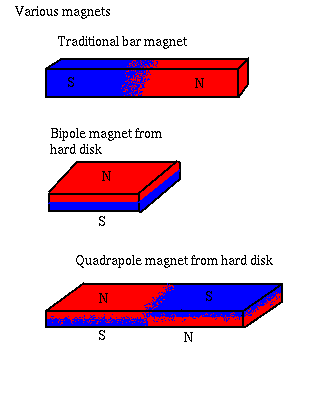
The magnets sitting on the platter. These were arranged so that the poles alternated. Here I should note that hard disk magnets are rather curious beasts by design, the small squarish ones are bi-pole magnets, and flat - with north on top and south on the bottom (or vice versa) - like a very short bar magnet. The larger ones are quadrapole magnets, on one half north is on top, south is on the bottom (see picture)

The flat nature of hard disk magnets of course leads to a nice low-profile design.
[picture to come]
The magnets being glued in place.
[picture to come]
All magnets glued in place. Neatness isn't a necessity here, as long as the magnetic focal points are roughly equally spaced.
Fixing the hub to the wheel
Time for some engineering. The hole in the center of the platters is just big enough to fit over the hub of the rear wheel, but a little too big. I will also want it a few mm out from the base of the hub because I want to build a custom electromagnet that will fit around both sides (and form a nice closed magnetic field). Spacers will be required here, but not tonight because it's midnight and I can't fire up any heavy machinery without waking the neighbors.
coil design
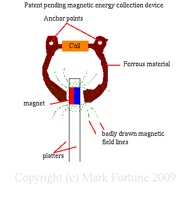
The design of the coil is fairly simple, a ferrous former will be anchored to the bike frame to focus as much of the magnetic juice through it as possible. A coil in the center will convert the magnetic force into usable electrical energy. The main design considerations for this are that the former will need to leave enough space to allow the rear wheel to spin without catching on the former. Also the former must be rigid enough to resist warping from the magnets (they are seriously strong), otherwise the hub will make horrible scratchy sounds and slow down my cycling.
Finally a perfect former is not made of solid metal, instead it is made of many thin laminated layers of metal to prevent eddy currents interfering with the magnetic field, however since I lack the time, resources and shear motivation to do this, a solid lump of metal will do.
Since I have decided on building my own coil, I am able to specify the output power. at a wheel circumference of ~ 1m, and a leasurely pace of 1m/s I would like to output at least 5v @ 500mA RMS. I will be using 26AWG wire for the coil (since that's what I have the most of laying around) which is rated at 2.2A
[Picture to come]
I found these two metal brackets laying around and doing nothing, and figured they would make a perfect former, after a little bending and shaping of course.
[picture to come]
The brackets bent into shape.
[picture to come]
Brackets fixed together, ready to take the coil
[picture to come]
many hours of manual coil winding later...
Circuit design
The output from the coil will be AC, so this needs to be rectified and smoothed before it can be used. The output voltage will also vary considerably at different speeds, and this too needs to be regulated to ensure that lights are not blown.
Once the generator itself is in place, I will run it at full speed to get its peak voltage and power output, then spec components accordingly - although if the output runs into hundreds of volts at high rpms (unlikely) I will probably invest in a neon bulb to a) act as a surge arrestor and b) to look damn cool.
Another thought occurs that I can take the raw output from the generator, and use it as the input to a speedometer circuit. That would also be very cool.
[More to follow as i'm really making it up as I go along]
Balancing the hub
Because of the lack of precision engineering that went into making the hub, the center of mass is not going to be in the center. To counter this it is necessary to add random weights at specific points, this will avoid nasty vibrations at high speeds (I will probably use some 1p coins as counter balances).
Fixing the hub to the wheel
[Picture to come]
I figured this was an important step - the half assembled hub hanging off the wheel so I could get an idea of how much clearance was needed. Now to figure out a way to attach it to the wheel.
